A boat DC electrical system consists of the alternator, the battery, and the wiring, including circuit breakers in the main panel. All of these are made especially for marine use and differ from their automotive counterparts.
The DC system in a boat resembles that found in an automobile with the important difference that there is no chassis ground on a boat and, therefore, every electrical device has two wire connections: a positive wire for power and a negative wire—usually black—for ground. That second, negative wire is a return path to the battery, like what the chassis in a car provides.
Wiring
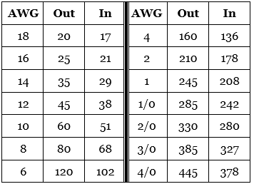
Marine grade wire used in boats is always stranded, so that it can flex without breaking, and each strand is tinned to block corrosion. That’s why it is so expensive. It should be at least 16 AWG (except within the panel where LEDs can be wired with smaller 18 AWG). It should be bundled and wrapped every foot or so and secured to something solid that does not vibrate.The table shows ABYC maximum allowable Amperage of wires for systems under 50 volts and insulation rated to 105° C, whether outside the engine compartment (Out) or inside the engine compartment (In).
Wire
color
Standards for wire color exist, although it is probably optimistic to expect that repairs and retrofits will always follow them.Yellow w/red stripe (YR): Starting switch to solenoid.
Brown/yellow stripe (BY) or Yellow (Y): Bilge blowers fuse or switch.
Dark gray (Gy): Navigation lights, or switched-on lights, and tach sender.
Brown (Br): Alternator field windings, charging indicator, or pump switch or fuse.
Orange (O): Ammeter input, accessory fuse or switch off of main panel.
Purple (Pu): Electrical instruments.
Dark blue: Fuse or switch for cabin or instrument lights.
Light blue (Lt Bl): Oil pressure sender to gauge.
Tan: Water temperature sender to gauge.
Pink (Pk): Fuel gauge sender to gauge.
Wire
connections
Wire connections can be either spliced and soldered, or crimped. If spliced and soldered, they tend to fail by fracturing at the joint, and so-called cold joints are a further problem. Use only a Western Union splice. If crimped, the wire tends to vibrate out of the connector. Use only marine grade ring-type connectors, never automotive grade or spade-type connectors, together with the correct crimping tool for the connector, and follow the manufacturer’s instructions.Use only the correct size connector for the gauge of wire. Smaller gauge is larger wire. Most connectors are color coded to match the wire gauge and the tool slot for crimping: red down to 18 gauge (maximum capacity at 12 volts is 10 amps), blue for 16 gauge (max 20 amps) or 14 gauge (max 40 amps), and yellow for 12 (max 60 amps) or 10 (max 100 amps) gauge. Never crimp the ends of the connector where there is no metal.
Never under any circumstances use household twist-on wire nuts. They have no place on a boat. When a Western Union splice is not wanted (eg, perhaps because the connection might need to be opened later, as on an instrument pigtail) two wires can be joined with crimped on butt connectors or with lever type connectors. The lever connectors, of which Wago 221 is the branded best choice, can attach more than two wires, and wires of different gauges, and can be opened to disconnect the wires as needed.
It might be tempting to solder, or "tin," the stripped ends of wires before connecting them; however, ABYC standards specifically prohibit doing this. Instead of being flexible, solder makes the stripped end rigid and therefore susceptible to vibration. The flexible-to-rigid transition becomes a likely failure point.
Voltage, current,
resistance, and power
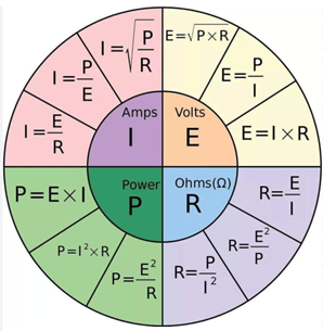
The electrical properties of voltage, current (denoted I from the French word intensité), resistance, and power (in Watts) are all related such that you can compute any one of them knowing any two of the other three.